Wednesday, April 15, 2009

stub calculation v.2


Photobucket Photobucket

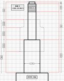
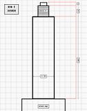
here are the two latest versions...on the left lowers the front by 1.25", the right by 1.5". the fatter part at the bottom is for the bump stop/bellows, and an unknown diameter until i have one to use. both versions require shortening the "native" threads of the KYB damper since theyre so short, and i figured 10mm between the end of the female threads and the shoulder/start of the male threads seemed about right. neither is to scale, although i tried to fake it by counting grid squares. the 20mm of shank on top is the approximate depth of the strut mount bearing, and i left the threads extra long so they could be trimmed to length then be fashioned with wrench flats. 

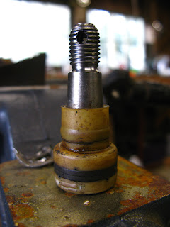
i'm leaning towards 1.25" so that i can add spacers if its too much, like grade 8 washers. after several days of searching online for various bump stops and bellows i've learned that in the aftermarket they're basically all made by KYB and are universal fit. all the bellows are the same and the only variation, for the most part, is in the shape of the bump stop. KYB's range of products are designed to fit a huge variety of vehicles, so i just picked one with the shortest bump stop, SB 103:


i'm not sure exactly how i will attach it yet, but it should arrive early next week from rockauto.com. once its in my hands i can finalize the shape of the bottom edge of the stub and take my plans to the machinist...

Sunday, April 12, 2009

stub calculation

the primary thing that determines the ride height of the front end is the distance between the axle and mounting point of the strut at the body. a shorter distance here will lower the car by whatever that is, for the most part. now that the upper assembly is finished on the new, modified struts, i can compare it to the original:


on the left is original, 650mm. on right is modified, 590mm. 60mm is roughly 2 1/2", or about 1" more than i want, so that should mean that the stub needs to have a length from its base where it threads onto the damper to its shoulder where it contacts the strut mount/bearing of 1". that would mean that with it (the stub) my new length between steering knuckle and mount would be 1 1/2" shorter than stock, resulting in a lowering of the front end by that amount. 

heres the rub: a length of 1" (ignore the threads on top for now) is less than the necessary thread depth to screw onto the damper fully...it needs 37mm, and thats just under 1 1/2". 


basically, the shortest i can make it from end to shoulder is 41mm; that would leave just 4mm of material above the female threads before the upper shoulder and male threads, the same as the wall thickness. the longest would be 61mm; that would actually duplicate the same ride height its always had, and any more than that and i would be lifting the front end. 
  thats a maximum lowering of just 20mm. somethings not right...

Wednesday, April 8, 2009

strut rebuild...upper assembly


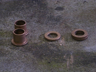
i got the spring plates bored the other day and found washers to use as shims at McGuire Bearing...they're actually part of a thrust bearing kit that they were willing to seperate. the washers at typical hardware stores were too large in OD to fit inside the bearing cone...

L to : 0.124, 0.062, 0.031, 0.045


the one next to the Mazda bearing is a machine bushing from the hardware store; stacked up they all look like this:


inside the bearing cone:


and with the Mazda bearing, the stack (0.262") allows the top face to just barely clear the cone:

installed:


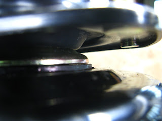
the skirt of the bearing cone also makes very light contact with the spring plate, but only enough to prevent excessive side loading. when bolted up like this, the strut mount spins freely with only a slight scraping on the plate:


here you can see another jig made from an obsolete bicycle suspension tool:


the 2-piece brass/aluminum threaded collar was used for installing either bearing races or seals in a Cannondale Headshok, i think. i saved it from the metal recycling and its been a benchtop pen holder ever since...now its taking the place of the coil, applying force to the underside of the spring plate while i'm mocking all this up.
 
  now that the mount/upper assembly is finished i can calculate the adapter/stub dimensions...

centerlink assembly...again


i started completely over with new materials and a couple design changes yesterday and finally reached a good result. the only thing i havent done yet is seal it with Permatex/silicone, but otherwise i consider it done. 

i used a flanged bearing sleeve in place of several washers, which also bypassed the need to individually resize their IDs to match the taper. the size was 5/8 x 3/4 x 1 (ID x OD x flange OD) which is within a few thousandths of whats needed. the end of the centerlink does need to be enlarged a little to allow the sleeve to pass through, but again its only a few thou... maybe 1mm. this will have to be done with a Dremel. use the biggest sanding drum that will fit inside the hole to minimize any out-of-roundness and make very brief passes; sand, measure, test fit, repeat. i was possibly too careful so it took me quite a while, but it is important to get the diameter as close to perfectly round as well as square (in other words, the walls of the hole are perpendicular to the face).


since i dont have a lathe or any machine tools i had to come up with a few poor-bastard substitutes like this thing. its a 5/8" bolt and a sleeve of 5/8" conduit cut with a pipe cutter to act as a spacer. with the nut tight and the bronze bearing positioned on the unthreaded shank of the bolt, it's held rigidly on-center. that means you can hold it up to a belt sander, turn it slowly by hand, and keep it reasonably true:


once the flange OD was down to 25mm, i made a crude sanding drum/flap wheel out of a piece of threaded rod and a strip of emery cloth. with a slot cut in the end, the strip can be wrapped around to the right size. 


this part also took a very long time, but was much better than using a Dremel because it guaranteed a consistent diameter. it also helped the fitting to polish the pin in this area, too. i used red scotchbrite then ultra-fine steel wool, like a 0000 grade. 


heres the finished product... i think the surfaces turned out pretty good considering the crude tools...where i really lucked out was in its length; along with an extra 1/16" washer and a beveled face, once installed in the centerlink the protruding sleeve is exactly the dimension i measured between the arm and the 'link: 0.458". boo-yah. 


the only other changes i made were to the cap. i bought two 8x12" sheets of galvanized shingle/flashing at Home Depot and tried a few other ways of forming the cap...


my favorite looking one is in the lower left corner, but they were all too wide, still, and interfered with the ears of the snap ring, so i jusy kept shrinking the size of the washer until i wound up with this:

sanded down to 25mm-ish, 


and finally, with snap ring:


it was so tight with the cap on that i had to use pliers to squeeze the snap ring all the way in its groove. 

now i get to do it all over again for the other side...

Sunday, April 5, 2009

centerlink assembly


  i went to the biggest hardware store in the area and sat down with my calipers at the bronze bushings and came up with this assortment. the pin measurements were .986" for the OD (the cavity size, actually 25mm) and an ID range of .536" - .636" (the taper). so thats basically 5/8". they only had two thicknesses (1/16 and 1/8) and they were $2.50 each, so i tried to get only what i needed for one side. i think it came out to around $25 because i used so many thin ones...
  the process of sanding/grinding each washer down to the right diameter is incredibly tedious. luckily its not a lot of material to remove, but it does take a lot of care to keep a perfect circle. i made a crude mandrel out of a BMX axle and an old suspension bushing and put it in the drill press:


  the ID was sized with a dremel tool using a 60 grit sanding drum. i used the largest size that would fit inside the original 5/8" hole...that kept the out-of-roundness to a minimum. this is my first batch. later versions had one more 1/16" washer and a beveled edge on top for a tighter fit:


assembled (as above) with 1" snapring:


this setup resulted in nearly 1/16" /0.060" of lateral play and nearly as much axial, so something was clearly not right. i started to feel like a chump for cutting apart a perfectly tight, sealed joint just to replace some nylon that might have cracked in another 20 years. it seems to me that by "solving" the nylon problem you just create a new one: sloppy pins. 
out of morbid curiosity i decided to spend the rest of the day trying to make a new cap out of some tin flashing i found in the basement. 

here you can see some of the early attempts behind the final draft:


most of that shape was thanks to another obscure bicycle suspension tool i had lying around. i'm not even sure what it was for originally, but it served as a perfect anvil:


the rest of the final shape was achieved with a small ball-peen hammer, a socket, and the head of the pin itself:


there are a couple issues i have with the cap...first, ideally it would be the same size (OD) as the groove that the circlip fits in so that it stays centered and covers everything. but it has to be smaller than that to fit past the opening (so basically the diameter of the cavity, or 25mm) and as a result its a loose, wandering fit:


 the other thing is that the dome size is just barely smaller than the opening, so it interferes with the ears of the circlip. also, i dont see how this would be any less susceptible to moisture issues without dipping the whole thing in plasti-dip or permatex...


in the end i made multiple versions to try and find just the right combination that would give a tight joint and never really found it. i did take a break from the internal parts and work on the external, tapered ones for a while. this was pretty straightforward...only one diameter to worry about and all i needed to do was keep stacking until it was the same as the gap i had measured  with the arm torqued on. it was so close to 1/2" that i just took the last washer and sanded one face of it flat on the bench til it was right, then tightened the arm on to force them all together:


i'm not totally sure about this part either, so i may redo one or two of the washers to get the stack height right. 

so after $60 in bronze washers and dremel parts and 3 days slumped over the vice all ive got is a really sore back. i dont think i'm going to do this to the NOS centerlink. i'll make a bushing for the gap, but not the insides. i just dont see how its an improvement.
Friday, April 3, 2009

centerlink disassembly PART 2


heres a drawing of the centerlink pin & bushing using lineform

  the gold-colored,  outlined graphics are the nylon bushings to be replaced with bronze...the best/worst part about it is that the stack of washers for the gap between the arm & link (the 0.4625" dimension) will need to be sized according to the taper of the pin...this basically means getting an assortment and sitting down with a dremel for a few hours and carefully grinding their IDs to match the taper, one at a time, so they're nice and tight...crap. 

centerlink disassembly

  i decided to go ahead and take the centerlink that came out of my car apart today...what a heinous task. i think i went through 3 cutting wheels and by the time i was done i had totally massacred the body, and it may not be useable...
  the backside of the ends are covered with a fairly thick steel cap that is actually two seperate pieces; the "dome" and a ring around the outside edge that is swaged in place. at first i thought it might be possible to just cut off the ring and hammer the pin out with all the guts, and maybe this would preserve the domed cap for reuse... wrong. you must cut out the center cap only without disturbing the ring or you lose what holds everything securely together...

here you can see the early stages...each "quadrant" is a crescent-shaped sliver of whats left of the cap:


after a while they started to come loose and could be pried out:


and then a huge chunk let go:


heres whats left of the cap and the external part of the nylon bushing (what the piman/idler arms tighten down against):


this is what the whole thing looks like when assembled inside the 'link ends:


and each part, L to R: main bushing, pin, centering rings, and the other bushing that is just under the cap:


a very important part of this is to first measure what will be the height of the new bushing by torquing the arm (pitman or idler, whichever side youre working with) and carefully measuring the gap after youve removed the nylon sleeve with a knife so it looks like this:


 of course, i forgot to do this part first, while the pin was nice and tight, so i had to fake it by using a small puller to hold it firm while taking measurements (measure in inches, it will make shim/bushing shopping much easier):


  i may have put a little too much force on it and squished the nylon a bit more than it normally is, so my measurements (taken at 4 points around its circumference) were higher than some others ive seen on the forum and they varied by about 0.010", but i'm using a stack of bronze washers so i'll be able to adjust...the average was 0.4625". 

once the guts were out i could see what a mess i'd made of the end...i had cut a notch out and tried to chisel the ring off:


without the swaged end to keep the pin & bushings in place they would be free to just pop right out the backside, so i might have to devise something else...maybe just weld it shut...luckily i still have the NOS 'link, so i might overhaul that one properly (now that i know what not to do) and use it on the car. then i can repair this one once i figure out the best way. it may work better to use a very small grinding wheel or burring tool than a wheel...less collateral damage...


Thursday, April 2, 2009

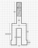
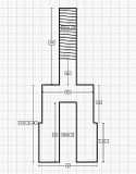
strut damper diagrams

PhotobucketPhotobucket   

  i found a demo for a drawing application that works with my out-of-date Mac and drew up a couple of diagrams of the two strut dampers just for comparison... it took a while to learn the (cocked-up) interface, but i finally have some decent technical drawings of what i'm working with. they're not to scale so the visual proportions are all off, and i rounded to the nearest 1/2 mm.  just an exercise, really.