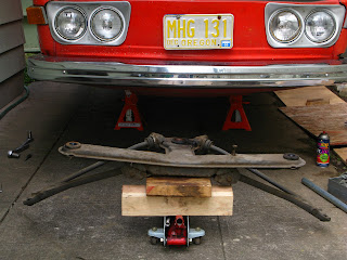
once the subframe was removed the level of wear on the entire suspension/steering was clear: totally fracked. both control arms made a shrieking noise when moved through their travel and the radius arms just clanked around inside the through holes at the tail of the subframe. i couldnt even see any bushing material at the pivot:
the OE bushings were a rubber sleeve bonded to a knurled steel insert that was pressed into the arm:
the axle hammered out, but the rubber had to be cut out with a hacksaw:
leaving the bare steel sleeve inside the arm:
that was the easy part. unfortunately, years of driving with worn bushings had ovaled-out the ends of the opening, giving a range of diameters depending on where it was measured, so 4 individually-sized bushings (two per arm) had to be made. i took two measurements at 9oº to eachother at each opening and used the average to size the OD of the bushing.
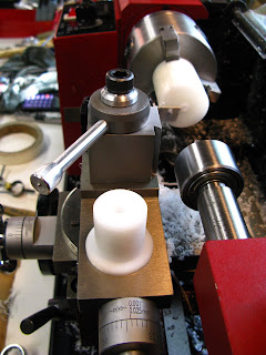
the bushings were made from 1.5" Delrin rod. my first attempt was made by turning down the outside where the press fit into the arm is, center drilling the end, then parting it off and drilling/boring the hole last. after parting, the piece was flipped around, the chuck jaws changed from external to internal, then drilled and bored from the backside. i didnt think it would make much difference, but it did, and i ended up with a bored hole that was not concentric with the OD. this pic is in between turning and boring operations...the bushing is on top of the compound rest and the parting blade can be seen against the stock:
this method also resulted in dramatically tapered ID, for some reason. the only reason i could come up with is that the work was held in the chuck by the small OD (for surface area) and i think the clamping pressure of the jaws compressed the material enough that when the boring bar passed through it, more material was removed due to the compression, and once it was removed from the chuck, it sprung back to normal and effectively enlarged the inner diameter.
for the second bushing i tried a different approach that worked well enough to use it for the rest; i did all turning, drilling, and boring in a single set up, then parted at the very end. this gave a much more concentric result, but i still had a frustrating taper on both the OD and ID...
the next step was to press the bushing onto its axle, using it as a mandrel, then make the final cut on the OD to the press fit dimension. this ensured they were concentric:
the very last step was to press them into the arm then run a reamer through... i found a 20mm used reamer on ebay for $17 that was still good enough for plastic... i tried doing it by hand at first, then used the slowest speed on the lathe...
it actually fed itself and gave a really good finish... i would have never tried something like this if i wasnt able to gradually start the motor from a dead stop thanks to the variable speed...
the axles for each side had to be cleaned up and polished before they would slide in, so i made a simple mandrel for them for sanding:
once i got my method sorted out things went pretty quick; i think the first bushing took me a couple days to make, the second one took most of one day, and the last two i made in just a couple hours.
nice...
i also replaced the radius arm centering rings with custom made Delrin ones... i'm not sure it was absolutely necessary, but it seemed like i was on a roll...
i've been painting for the last couple days and its finally all ready to go back together...


